FSAE brake pedal
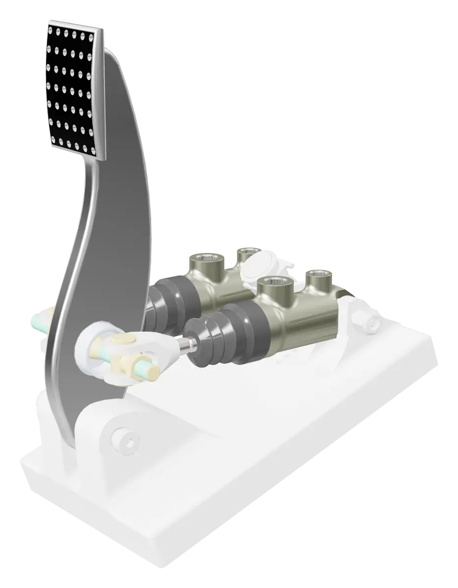
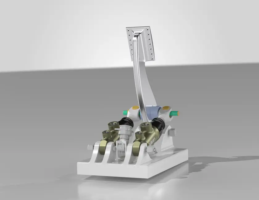
A complete brake pedal assembly for a Formula SAE electric car, designed for the AME27 Apprentice Mechanical Design Challenge.
2.13factor of safety at 2 kN
| RoleSole designer: research, hand calculations, CAD and FEA | DatesFall 2026 | |
| ContextAME27 Apprentice Mechanical Design Challenge, Texas A&M Formula SAE Electric | ToolsSolidWorks, SolidWorks Simulation, Hand calculations | |
The assembly in 3D
Live modelLoads when you scroll here
Drag to orbit · scroll or pinch to zoom · right-drag to pan
Click a part on the model, or pick it from the parts list.
Requirements and architecture
Rule T.3.2.2: the pedal must withstand 2,000 N at the pedal face without failure of the brake system, pedal box, chassis mounting or pedal adjustment.
The rules require two master cylinders, so I chose Tilton 78-Series (78-700) units on independent front and rear circuits, linked by a Tilton 72-250 balance bar. They come with return springs built in, which kept the design simple and compact.
After reading the rules I split the parts into what to buy (master cylinders, shoulder screws, bearing, locknuts) and what to design (pedal arm, base, switch holder).
Pedal geometry and hand calcs
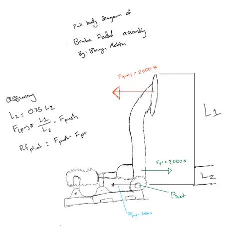
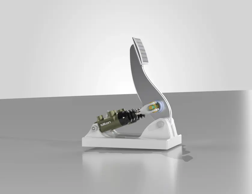
Floor-mounted pivot with the balance-bar clevis and the pad on the same side of it, the common FSAE pedal-box layout.
Clevis 45 mm above the pivot and pad 180 mm from it: a 4:1 pedal ratio, inside the typical FSAE range of 4:1 to 6:1. I kept the arm short to protect stiffness.
The pivot is a pin and cannot react a moment, so the peak moment sits at the balance-bar bore. The 12 mm arm tapers to be deepest there.
- 180 / 45 = 4 : 1
- Pedal ratio
- Typical FSAE range is 4:1 to 6:1
- M ≈ 270 N·m
- Peak moment at the balance-bar bore
- 2,000 N × (180 − 45) mm = 2,000 N × 0.135 m
CAD and FEA
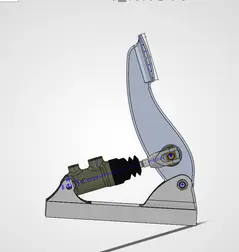
Imported the bought parts into a SolidWorks assembly and placed them with mates before drawing the arm, so its geometry was set by real hardware.
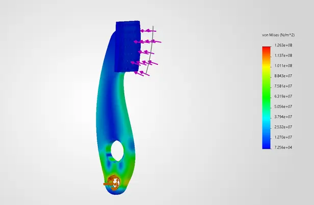
Ran a first FEA at 2 kN on the extruded profile, then added fillets for a lighter, easier-to-machine aluminum part and a tapered rectangular pad that spreads the load. The final study gives a factor of safety of 2.13.
Designed the base to be milled from one aluminum block, with arches and shoulder screws so the pedal and both master cylinders can rotate.
Found where over-travel occurs (36°) and designed an adjustable holder for the brake over-travel switch, a McMaster push/pull switch that stays latched once tripped, as the rules require.
Results
- 2.13
- Factor of safety at 2 kN
- ≈ 270 N·m
- Peak bending moment
- 4 : 1
- Pedal ratio
- 36°
- Over-travel trip angle